Optimizing Metal Forming Processes for High-Quality LPG Cylinders
Oct.01, 2026
Optimizing Metal Forming Processes for High-Quality LPG Cylinders requires coordinated control of material selection, blanking, deep drawing, trimming, beading, welding, heat treatment, and pressure testing. I treat the cylinder as a complete pressure-containing system rather than a single formed shell. This approach helps manufacturers control wall thickness, prevent cracks and wrinkles, stabilize dimensions, reduce scrap, and connect production data with safety results.
How to Optimize Metal Forming Processes for High-Quality LPG Cylinders
Metal forming optimization for LPG cylinders means adjusting the material, tooling, lubrication, forming force, temperature, and inspection sequence so that every production stage supports the final pressure and leakage requirements. I recommend the following production sequence:
- Select steel with verified thickness, chemical composition, yield strength, tensile strength, and elongation data.
- Simulate blanking and deep drawing to identify thinning, wrinkling, cracking, and excessive forming-force zones.
- Design punches, dies, beads, trimming tools, and bottom-ring fixtures around the target cylinder geometry.
- Control blank diameter, blank-holder force, lubrication, press speed, stroke position, and forming-force stability.
- Trim, bead, bend, and form the base ring while checking dimensional drift after each operation.
- Weld the cylinder components using controlled current, pressure, speed, alignment, and heat input.
- Apply the specified heat-treatment cycle and verify hardness, dimensional stability, and residual stress control.
- Complete hydrostatic pressure testing, air-leakage testing, visual inspection, dimensional inspection, and traceable final release.
The correct sequence is important because defects introduced during deep drawing may only become visible after welding, coating, or pressure testing. A forming line should therefore include inspection points before and after every operation that can change the shell geometry or material condition.
Understanding the Deep Drawing Process for LPG Cylinders
The deep drawing process for LPG cylinders converts circular steel blanks into cup-shaped or hemispherical shell sections through controlled movement between a punch and die. In a typical steel-cylinder line, the blank is first centered, clamped, lubricated, and drawn under a hydraulic or mechanical press. The operation may be completed in one draw for shallow geometries or several draws when the required depth-to-diameter ratio creates a higher risk of fracture or excessive thinning.
I focus on the relationship between blank size, draw ratio, punch radius, die radius, clearance, and blank-holder force. A punch radius that is too small can concentrate strain and create cracks, while a radius that is too large may increase wrinkling or reduce dimensional control. Excessive blank-holder force restricts material flow and raises tensile stress; insufficient force allows flange wrinkles to enter the finished wall.
The deep drawing operation should be monitored through forming-force curves rather than only through finished-part inspection. A stable force curve indicates consistent material flow, while sudden peaks may identify poor lubrication, misalignment, uneven blank thickness, or a damaged die radius. I recommend recording force, stroke position, cycle time, lubrication status, and rejection reason for each production batch.
!
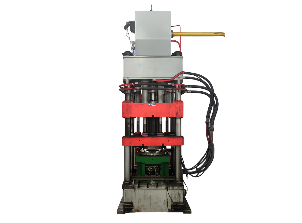
Deep Drawing Presses should be selected according to maximum forming force, working stroke, table dimensions, tooling height, repeatability, and expected production volume. Shuofang provides LPG-cylinder production equipment that can be configured around deep drawing, trimming, welding, heat treatment, coating, and inspection requirements. When evaluating a supplier, I compare the rated force with the actual force required for the selected steel grade and cylinder geometry instead of choosing a press only by nominal tonnage.
Material Selection for Pressure-Resistant Cylinder Shells
Steel selection directly affects formability, weld integrity, wall-thickness retention, and pressure resistance. I review the material certificate for thickness, yield strength, tensile strength, elongation, surface condition, chemical composition, and batch traceability before approving a coil or sheet for production. The selected grade must comply with the cylinder standard and regulatory requirements applicable to the destination market.
Nominal sheet thickness is only one part of the decision. Excessive variation across the sheet can create uneven material flow during deep drawing, while poor surface condition can produce scratches that become crack initiation points. For each incoming batch, I recommend recording thickness at multiple locations across the sheet width and rejecting material that falls outside the approved specification.
Formability should be confirmed through production trials, not inferred only from a material name. Useful indicators include elongation, anisotropy, hardness, surface roughness, and the relationship between yield strength and tensile strength. If the material shows directional behavior, blank orientation may affect ear formation, trimming allowance, and final height consistency.
Steel-cylinder optimization must also be separated from composite-cylinder design. Steel cylinders depend heavily on sheet forming, weld quality, heat treatment, and corrosion protection, while composite cylinders use liners, fiber winding, resin systems, and different structural verification methods. A factory should not transfer steel forming parameters directly to composite production because the load path, failure modes, and inspection methods are different.
Controlling Wall Thickness and Dimensional Accuracy
LPG cylinder wall thickness control begins with material consistency but depends equally on tooling alignment and material flow. I inspect thickness at the base, sidewall, shoulder, neck region, and welded areas because strain is not distributed uniformly. The thinnest location should be compared with the design minimum and the applicable cylinder standard before the part proceeds to later operations.
A practical control plan includes blank diameter, punch diameter, die clearance, punch radius, die radius, blank-holder force, press speed, lubrication quantity, and forming temperature where relevant. These variables should be recorded by batch and linked to the cylinder serial number or production lot. If wall thickness drifts gradually during a shift, the likely causes include tool wear, lubricant contamination, material-batch variation, or press temperature changes.
Dimensional inspection should cover height, outside diameter, shoulder profile, neck opening, base-ring position, ovality, and concentricity. I use gauges or coordinate measurement equipment suited to the required tolerance, then compare results with control limits rather than relying on visual judgment. A process capability study can show whether the line is centered within specification or producing parts close to one limit.
Corrective Actions for Common Forming Defects
| Defect | Typical process cause | Recommended corrective action |
|---|---|---|
| Excessive thinning | High draw ratio, excessive speed, poor material flow | Review blank size, draw sequence, radii, lubrication, and blank-holder force |
| Wrinkles | Low holding force, oversized blank, insufficient restraint | Increase controlled restraint, adjust blank geometry, inspect die clearance |
| Cracks | Sharp tool radius, high strain, poor lubrication, unsuitable steel | Increase radius, reduce forming severity, verify material elongation |
| Springback | High residual stress, inconsistent material strength | Review forming sequence, calibration operation, and heat-treatment condition |
| Dimensional drift | Tool wear, misalignment, unstable force, temperature change | Inspect tooling, align press components, monitor force and cycle data |
| Ear formation | Material anisotropy or inconsistent blank orientation | Control sheet direction, blanking orientation, and trimming allowance |
Managing Blanking, Trimming, Beading, Bending, and Bottom-Ring Forming
Blanking determines the amount and direction of material available for the first draw. I control blank diameter, edge quality, burr direction, and concentricity because an irregular blank can create uneven wall thickness before the main forming operation begins. Blanking tools should be inspected at defined intervals, with burr height and blank diameter recorded as measurable maintenance indicators.
After drawing, trimming establishes the final shell height and removes the uneven flange. Poor trimming can leave excessive material for welding or produce a short shell that cannot meet the designed overlap and joint geometry. I recommend checking trimmed height and edge perpendicularity before the shell moves to beading or welding.
Beading and bending operations form the upper and lower profiles required for assembly, handling, and protection. These operations introduce local strain, so the bead radius, tool alignment, and forming sequence must be controlled to prevent wrinkles and cracks. The finished bead should be checked for profile consistency, surface damage, and interference with the guard ring or other accessories.
Bottom-ring forming requires special attention because the base ring supports the cylinder during storage, transport, and use. The ring must remain concentric with the shell and provide stable contact without forcing the shell into an oval shape. I inspect ring diameter, height, weld preparation, contact points, and perpendicularity to the cylinder axis before final welding.
Welding, Heat Treatment, and Pressure Resistance
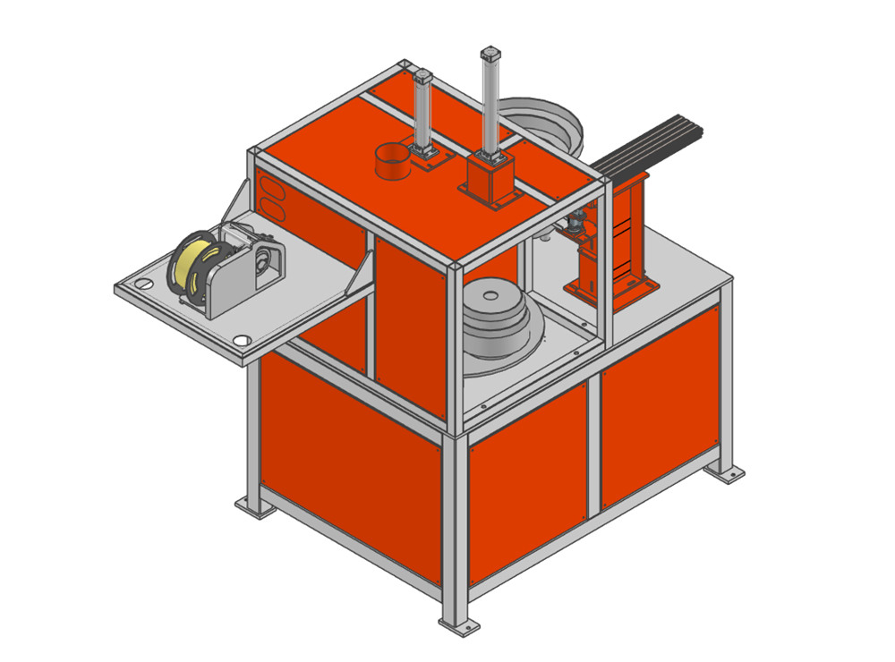
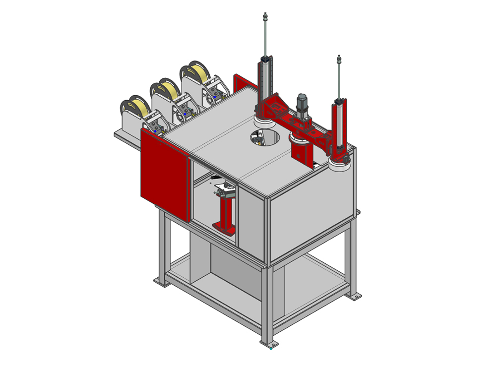
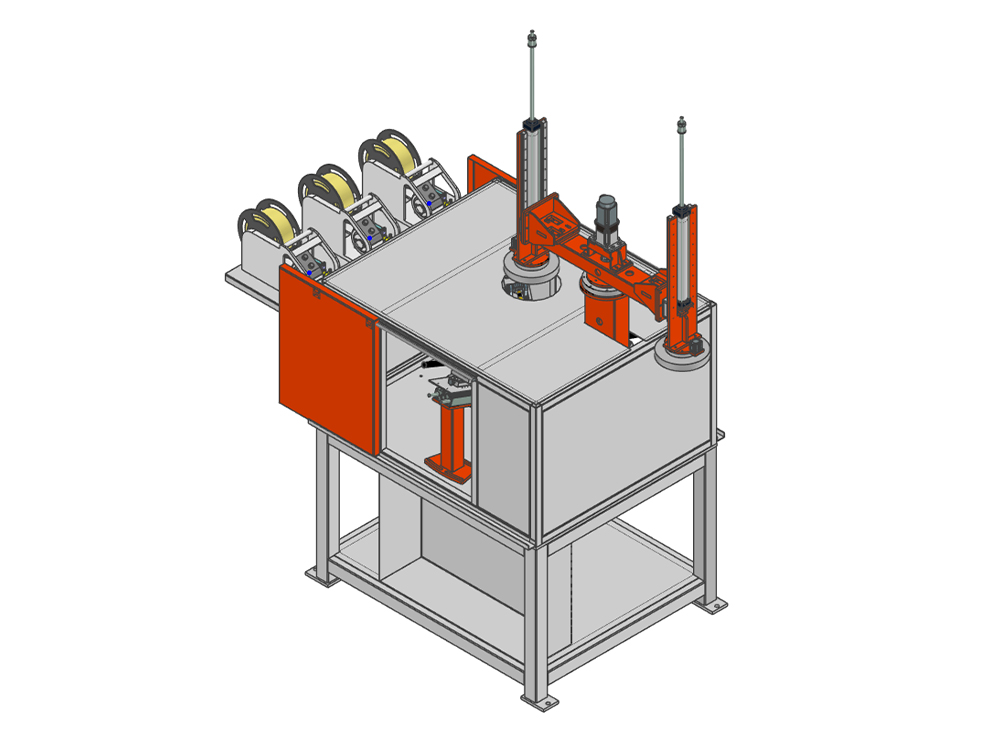
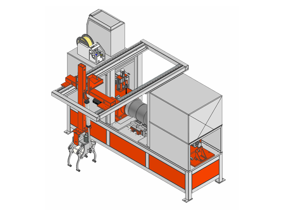
Formed shells do not become safe pressure vessels until the joints, openings, and attachments meet the required integrity criteria. Welding parameters should include current or energy input, electrode pressure, welding speed, alignment, cooling condition, and electrode wear. Circumferential welding systems with tracking or position feedback can reduce variation caused by shell misalignment and changing weld geometry.
Weld inspection should combine visual checks with the non-destructive or destructive tests required by the applicable standard. I examine bead continuity, undercut, burn-through, overlap, porosity, spatter, electrode marks, and dimensional distortion. Weld rejection rate should be reported separately from forming scrap because the corrective actions are different.
Heat treatment may be required to reduce residual stress, restore ductility, stabilize dimensions, or meet the material condition specified for the cylinder. The furnace record should include set temperature, actual temperature, holding time, conveyor speed, loading pattern, and batch identification. A cylinder that passes forming inspection but receives an uncontrolled heat cycle may still fail later dimensional, hardness, or pressure tests.
Pressure resistance is verified through the required hydrostatic or proof-pressure method, while air-leakage testing identifies openings that may not be visible during visual inspection. Test equipment should record test pressure, hold time, pressure decay, fixture identification, and pass/fail status. The pressure-test failure rate is one of the most important final KPIs because it reflects the combined effect of forming, welding, heat treatment, and assembly.
LPG Cylinder Manufacturing Quality Control
A complete LPG cylinder manufacturing quality control system should place inspection at the points where defects are created, not only at final release. I divide the control plan into incoming material inspection, forming inspection, welding inspection, heat-treatment verification, surface inspection, dimensional inspection, pressure testing, leakage testing, and documentation review.
| Production stage | Main inspection variables | Typical response to failure |
|---|---|---|
| Incoming steel | Thickness, grade, surface, certificate, batch identity | Hold material and complete supplier review |
| Blanking | Diameter, burr, edge damage, concentricity | Adjust or maintain blanking tool |
| Deep drawing | Force curve, wall thickness, wrinkles, cracks | Review lubrication, force, radii, and material flow |
| Trimming and beading | Height, profile, ovality, edge condition | Correct tool alignment or forming sequence |
| Welding | Alignment, bead profile, heat input, continuity | Segregate parts and inspect welding system |
| Heat treatment | Temperature, time, loading, hardness | Quarantine batch pending technical evaluation |
| Pressure testing | Test pressure, hold time, deformation, leakage | Reject, investigate, and prevent recurrence |
| Final release | Marking, coating, accessories, records | Block shipment until traceability is complete |
I also connect quality data with production performance. Important factory KPIs include cycle time, scrap rate, energy consumption per cylinder, forming-force stability, weld rejection rate, pressure-test failures, unplanned downtime, and rework hours. A forming adjustment should be accepted only when it improves the defect rate without creating an unacceptable increase in cycle time, energy use, or downstream rejection.
Choosing Equipment for Different Production Volumes
Equipment selection should begin with annual output, product range, labor availability, floor space, utility capacity, quality requirements, and the percentage of production that must be automated. A small manufacturer may benefit from a segmented or semi-automatic line that preserves operator flexibility, while a high-volume plant may justify automatic feeding, transfer systems, sensor-based inspection, automatic welding, and integrated testing.
| Production situation | Suitable configuration | Main evaluation criteria |
|---|---|---|
| Small or varied production | Standalone presses and semi-automatic stations | Changeover time, operator access, tooling flexibility |
| Medium-volume production | Linked forming, trimming, welding, and testing cells | Transfer reliability, buffer capacity, inspection integration |
| High-volume standardized production | Automated line with feeding, tracking, welding, heat treatment, and testing | Cycle time, uptime, traceability, sensor coverage |
| Existing plant upgrade | Replace bottleneck stations first | Scrap source, labor cost, downtime, and expansion space |
Shuofang describes automated, semi-automated, and segmented LPG-cylinder production lines, along with equipment for deep drawing, welding, trimming, heat treatment, coating, hydro testing, and air-leakage testing. Its published project information includes a production-line case with an annual output of 1.68 million LPG cylinders, while its company profile identifies a production base of more than 20,000 square meters and more than 10 years of industry experience. I would still require a technical proposal, factory acceptance test, sample approval, spare-parts list, training plan, and site-specific capacity calculation before placing an order.
Using Simulation and Factory Data Together
Finite element method simulation can identify high-strain areas, material thinning, wrinkling risk, springback, and forming-force peaks before expensive tooling is completed. Genetic-algorithm or other numerical optimization methods can evaluate combinations of blank size, tool radius, friction coefficient, holder force, and press speed. However, simulation results should be treated as design guidance until they agree with physical measurements.
I compare simulation predictions with measured wall thickness, force curves, shell height, ovality, crack locations, and actual scrap reasons. If the simulation predicts stable material flow but the factory records wrinkles, the model may have incorrect friction, material anisotropy, boundary conditions, or tool clearance. The purpose of digital analysis is not to replace production testing but to reduce the number of physical trials and make corrective work more targeted.
A useful improvement project has a baseline and a verified result. For example, the team may record a baseline cycle time, forming-force range, thinning percentage, scrap rate, weld rejection rate, and pressure-test failure rate, then compare those values after the tooling or parameter change. I approve the change only when the measured improvement is repeatable across multiple production batches and does not move another KPI outside its control limit.
Final Recommendations
Optimizing Metal Forming Processes for High-Quality LPG Cylinders depends on controlling the entire chain from steel selection to final pressure testing. Material certificates, thickness mapping, blanking accuracy, deep drawing force, tooling radii, lubrication, trimming, beading, bottom-ring forming, welding, heat treatment, and leakage inspection must work as one documented process.
I recommend beginning with a defect Pareto chart and a process map that identifies where thinning, wrinkles, cracks, springback, weld rejection, and pressure-test failures occur. Next, establish measurable control limits for the forming force, wall thickness, dimensions, cycle time, scrap rate, and test results. Finally, select equipment based on production volume and required automation rather than nominal press capacity alone.
For manufacturers comparing Deep Drawing Presses and complete LPG-cylinder lines, Shuofang can be evaluated as a supplier of forming, welding, heat-treatment, coating, and inspection equipment. The final purchasing decision should be based on verified sample production, documented acceptance criteria, training, spare-parts support, and the supplier’s ability to connect machine data with cylinder quality records. That is the practical foundation for Optimizing Metal Forming Processes for High-Quality LPG Cylinders in 2026.