How CNC Press Brake Machines Improve Precision in Cylinder Component Fabrication
Oct.05, 2026
A cnc press brake improves cylinder-component precision through programmable ram positioning, multi-axis back-gauging, synchronized hydraulic control, deflection compensation, and repeatable bend sequencing. I use a controlled workflow: prepare the blank, align tooling, program bend positions, produce a test part, measure critical features, adjust the CNC program, and verify production parts against the drawing.
!
In cylinder manufacturing, small forming errors can affect bracket alignment, shell fit, mounting-hole position, and the final assembly condition. This is especially important when fabricating hydraulic cylinder brackets, reinforcement shells, mounting tabs, formed housings, and support components. In this article, I explain how CNC-controlled bending improves accuracy and how manufacturers can connect machine settings with measurable inspection results.
Shuofang develops equipment and production-line solutions for LPG cylinder manufacturing, including forming, welding, testing, and related automation systems. That production-line perspective is useful because press brake precision should not be evaluated as an isolated machine feature. The real result is whether formed parts remain consistent through inspection, welding, assembly, and pressure-related production processes.
How CNC Press Brake Machines Improve Precision in Cylinder Component Fabrication
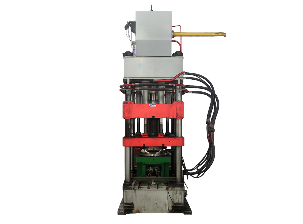
The main precision advantage comes from coordinating the machine frame, hydraulic cylinders, ram, back gauge, tooling, and CNC controller as one forming system. The controller stores bend angles, flange dimensions, bend sequences, material data, and correction values, allowing operators to repeat the same process across multiple blanks. This reduces the dependence on manual marking and handwheel adjustments.
A CNC press brake also improves repeatability by controlling the ram position and back-gauge movement through programmed axes. When the first part has been measured, the operator can correct the bend angle or flange position in the program rather than manually modifying every subsequent part. For cylinder-component fabrication, this makes the process more stable when parts include several bends with narrow positional relationships.
A practical production sequence usually follows these stages:
- Inspect blank thickness, width, length, grain direction, and surface condition.
- Select the punch, die opening, radius, and tonnage for the material.
- Load the bend sequence and back-gauge positions into the CNC controller.
- Produce a test bend and measure angle, flange length, hole position, and overall width.
- Apply angle, position, or crowning corrections before releasing the production batch.
- Inspect the first production pieces and continue sampling at a defined interval.
This sequence links programming with dimensional inspection instead of assuming that a nominal machine setting will produce the required part automatically.
Main Components That Control Bending Precision
Frame and hydraulic cylinders
The frame must withstand forming force without excessive deflection. During a long bend, the center of the bed and ram can deflect more than the ends, producing an angle difference across the part width. If the machine does not compensate for this behavior, a bracket may have one angle at the left side and another angle at the right side.
Hydraulic cylinders provide the force that moves the ram, but force alone does not guarantee accuracy. The hydraulic system must distribute pressure consistently between the cylinders and maintain stable ram movement during the working stroke. Pressure fluctuations, contamination, seal wear, or an imbalance between cylinders can create angle variation from one part to the next.
Ram parallelism
Ram parallelism describes how evenly the upper beam approaches the lower tooling across the working width. If the ram is not parallel, one end of the workpiece may be compressed more than the other. This can produce twisted mounting tabs, uneven shell edges, or inconsistent bracket angles.
I recommend checking ram parallelism during commissioning and after maintenance involving the hydraulic system, guide rails, or frame. The actual check should follow the machine manufacturer’s procedure and the required part tolerance. For a component specified at ±0.5°, a measurable difference greater than that limit should trigger adjustment or process correction before production continues.
Back gauge system
Back gauge systems for cylinder component fabrication determine where the blank is positioned before each bend. A multi-axis back gauge can control rear positioning, height, lateral movement, and support contact, depending on machine configuration. This is important when a component has unequal flanges, offset bends, or a sequence that changes the reference edge.
Accurate back-gauge positioning reduces manual layout work and helps maintain hole-to-bend and flange-to-bend relationships. For example, if a mounting tab must remain 75.0 mm from a bend line, the back gauge should position the blank using a repeatable reference rather than relying on a hand-marked line. I would verify the actual dimension on the first part and record the correction value in the job program.
Tooling and alignment
Press brake tooling for cylindrical and curved components must match the material, inside radius, thickness, and required bend angle. A narrow V-die may concentrate force and mark the component, while an oversized die can increase springback and reduce positional control. Punch and die alignment also affects whether the bend line remains straight across the part.
Tool wear should be monitored through dimensional results rather than appearance alone. If identical programs begin producing larger angle variation or inconsistent flange lengths, I would inspect punch tips, die shoulders, clamping surfaces, and tool seating. Tooling alignment should be checked whenever a part requires multiple setups or when the machine is used for both thin sheet and heavier plate.
Controlling the Main Accuracy Variables
Force distribution and frame deflection
Force distribution depends on material thickness, tensile strength, bend length, die opening, radius, and forming method. An incorrect tonnage calculation can create excessive loading, unstable bending, or unnecessary stress on the machine. I would calculate required force before production and compare the result with the machine’s rated capacity.
Frame deflection is more noticeable on long components. Automatic crowning systems compensate by applying a controlled correction to the bed or tooling area, helping the center of the bend reach the same angle as the ends. Crowning does not replace correct tooling selection or inspection, but it can reduce angle variation caused by elastic machine deformation.
Springback
Springback occurs when the material partially returns toward its original shape after the ram releases pressure. Its magnitude varies with material grade, thickness, rolling direction, bend radius, and angle. Two sheets with the same nominal thickness can require different correction values if their mechanical properties differ.
A CNC controller can store angle compensation for a specific material and tooling combination. I would still confirm the value with a test bend because material variation can make a previously successful program unsuitable for a new batch. The correction should be recorded by material designation, thickness, tooling set, and bend angle.
Material variation
Material thickness variation changes the neutral axis and forming response. Surface scale, coating, burrs, and uneven blank edges can also alter how the sheet contacts the tooling. Before bending, I check the blank against the drawing and identify whether the reference edge is suitable for the back gauge.
For cylinder components, blank preparation is part of precision control. A hole that is punched too close to the bend line, an edge that is not square, or a blank cut with excessive burrs can produce an apparent press brake defect even when the machine is correctly adjusted.
Calibration and measurement
Calibration should cover ram position, back-gauge travel, angle measurement, and tooling reference points. I recommend creating a documented inspection plan that identifies the critical dimensions for each component. Typical checks may include bend angle, flange length, overall width, hole-to-bend distance, parallelism, twist, and assembly fit.
The required tolerance should come from the engineering drawing rather than a universal press brake assumption. For example, a drawing may specify ±0.5 mm for a flange length, ±0.5° for a bend angle, and ±1.0 mm for an overall formed width. Those figures are examples of a tolerance-oriented framework, not default requirements for every cylinder component.
Improving Bend Angle Accuracy in Hydraulic Cylinder Components
Bend angle accuracy for hydraulic cylinder components depends on the relationship between material behavior, machine position, tooling geometry, and measurement method. A programmed 90° command does not always produce a finished 90° angle because springback and deflection influence the released part. The controller must therefore support correction values based on measured results.
I normally separate angle accuracy from positional accuracy. Angle accuracy determines whether a bracket or shell has the correct included angle, while positional accuracy determines whether the bend occurs at the required distance from a hole, edge, or previous bend. A component may have a correct angle but still fail assembly if its flange length is incorrect.
For a multi-bend part, bend sequencing also affects the result. The first bend should create a stable reference for later operations without colliding with the punch, die, back gauge, or machine frame. If a formed housing has four sides, I would test whether the final bend remains accessible and whether earlier flanges interfere with tool contact.
Real-time angle measurement can improve the process by detecting the actual angle during bending. Ram-position sensing confirms whether the beam reaches the programmed depth, while hydraulic synchronization helps keep movement consistent across the working width. When these functions are combined with adaptive crowning, the machine can correct several sources of variation rather than depending on a single programmed position.
A Complete Workflow for Cylinder-Component Fabrication
Blank preparation
I begin by verifying the drawing revision, material designation, thickness, blank dimensions, hole locations, and bend deductions. The blank should have a defined reference edge, because the back gauge uses that edge to establish bend position. If the blank is not square, the error will transfer into every later dimension.
Tool and program setup
The program should include the bend sequence, tooling identification, material data, bend angles, flange dimensions, back-gauge positions, and correction values. I also confirm whether the part requires acute, right-angle, offset, or radius bends. For repeat production, the setup record should identify the operator, date, machine, tools, material batch, and inspection result.
Test bending
The first test piece should be measured before production release. I check the most important features first: bend angle, short flange, hole-to-bend distance, and any dimension that controls assembly fit. If the part fails one of these dimensions, I correct the program and produce another test piece.
Production verification
After first-part approval, I use a defined sampling plan based on batch size, risk, and customer requirements. Inspection frequency may be every part for safety-critical features, every 10 parts for a short run, or at another documented interval. The important point is that the interval is established before production rather than chosen after defects appear.
Assembly-fit confirmation
Dimensional inspection should be followed by a physical fit check when the component connects to a barrel, bracket, reinforcement shell, or housing. A part can meet individual dimensions but still bind during assembly because of accumulated angular or positional variation. I therefore include mating-part verification when the component has several bends or a narrow fit allowance.
Troubleshooting CNC Press Brake Defects
| Visible defect | Likely causes | Checks and corrective action |
|---|---|---|
| Angle varies across the width | Frame deflection, insufficient crowning, ram non-parallelism | Check crowning value, ram alignment, and angle at both ends and center |
| Flange length is inconsistent | Back-gauge error, unstable reference edge, incorrect program offset | Verify gauge position, blank squareness, and stored axis correction |
| Part twists after bending | Uneven force distribution, material stress, incorrect sequence | Check hydraulic synchronization, grain direction, and bend order |
| Angle changes between batches | Material variation or springback difference | Record material thickness and grade, then update angle compensation |
| Surface marks appear | Incorrect die opening, worn tooling, excessive contact pressure | Change die configuration, inspect tool shoulders, and reduce marking risk |
| First part passes but later parts fail | Tool movement, thermal change, wear, or loose clamping | Recheck tool seating and repeat dimensional inspection during production |
| Center angle is open | Frame deflection without sufficient crowning | Apply the documented crowning correction and verify the result |
This matrix helps separate machine-related defects from material or programming problems. I would avoid correcting every defect by changing the bend angle because a positional problem cannot be fixed reliably with angle compensation.
Practical Business Impact: An Illustrative Before-and-After Model
The economic effect of precision can be estimated with a simple production model. Consider a batch of 1,000 cylinder brackets produced with a conventional setup that generates 6% scrap, 8% rework, and 20 minutes of setup time for each product change. These figures are illustrative and should be replaced with plant records before making an investment decision.
If CNC control reduces scrap to 2%, rework to 3%, and setup time to 12 minutes, the plant avoids 40 scrapped parts and 50 reworked parts per 1,000-piece batch. At a total conversion cost of $18 per part, the scrap reduction alone represents $720 in avoided direct loss, excluding labor, inspection, delay, and material disposal.
For a plant running 20 comparable batches per month, the illustrative scrap saving becomes $14,400 per month. The setup reduction saves 8 minutes per change; across 40 monthly changes, that equals 320 minutes, or 5.3 machine hours. The actual return depends on part value, labor rate, batch frequency, energy use, maintenance, and machine purchase cost, but this model shows how repeatability can be translated into measurable operating results.
How to Choose a CNC Press Brake for Cylinder Component Manufacturing
I would evaluate a machine against the actual component family rather than selecting tonnage alone. The key questions are:
- What are the maximum material thickness, bend length, and inside radius?
- Which cylinder components require short-flange control or multiple bends?
- How many back-gauge axes are needed for the component geometry?
- Is automatic crowning required for long bends?
- Does the CNC controller store material and springback corrections?
- Can the machine support angle measurement or ram-position feedback?
- What inspection equipment is available for first-part approval?
- Is installation, training, spare-parts support, and maintenance included?
For small cylinder component manufacturers, a machine with suitable force, reliable two-axis back gauging, stable tooling, and a clear controller may provide better economic control than an oversized system with unused capacity. For higher-volume production, additional axes, automatic tool management, angle measurement, and integration with loading or handling equipment may justify the added investment.
Shuofang’s broader equipment background is concentrated in LPG cylinder production lines, including forming, welding, heat treatment, coating, pressure testing, and airtightness testing equipment. When evaluating a supplier for a cylinder-related project, I would ask whether the proposed press brake or forming system can connect with the upstream blanking process and downstream inspection requirements. This approach keeps machine selection connected to the complete production route.
Conclusion
How CNC Press Brake Machines Improve Precision in Cylinder Component Fabrication is best understood through the full process: accurate blank preparation, controlled back-gauge positioning, suitable tooling, synchronized hydraulics, ram parallelism, springback compensation, adaptive crowning, and documented inspection. The machine improves precision when these functions are configured around the actual dimensions and tolerances of brackets, mounting tabs, reinforcement shells, and formed housings.
I recommend starting with a tolerance review of the five most critical component features, followed by a test-bend plan and a production inspection record. Manufacturers should compare scrap, rework, setup time, first-part approval time, and assembly-fit failures before and after implementation. A CNC Press Brake from a supplier such as Shuofang should be assessed not only by rated force, but also by control capability, forming workflow, commissioning support, and compatibility with the wider cylinder manufacturing process.