How Beading and Joggling Improve LPG Cylinder Assembly Accuracy
Oct.12, 2026
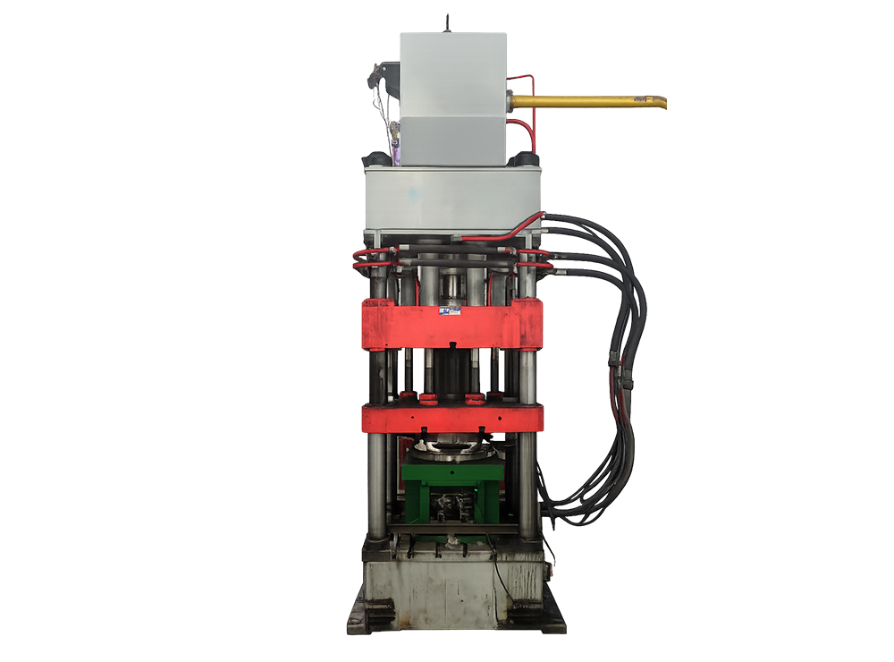
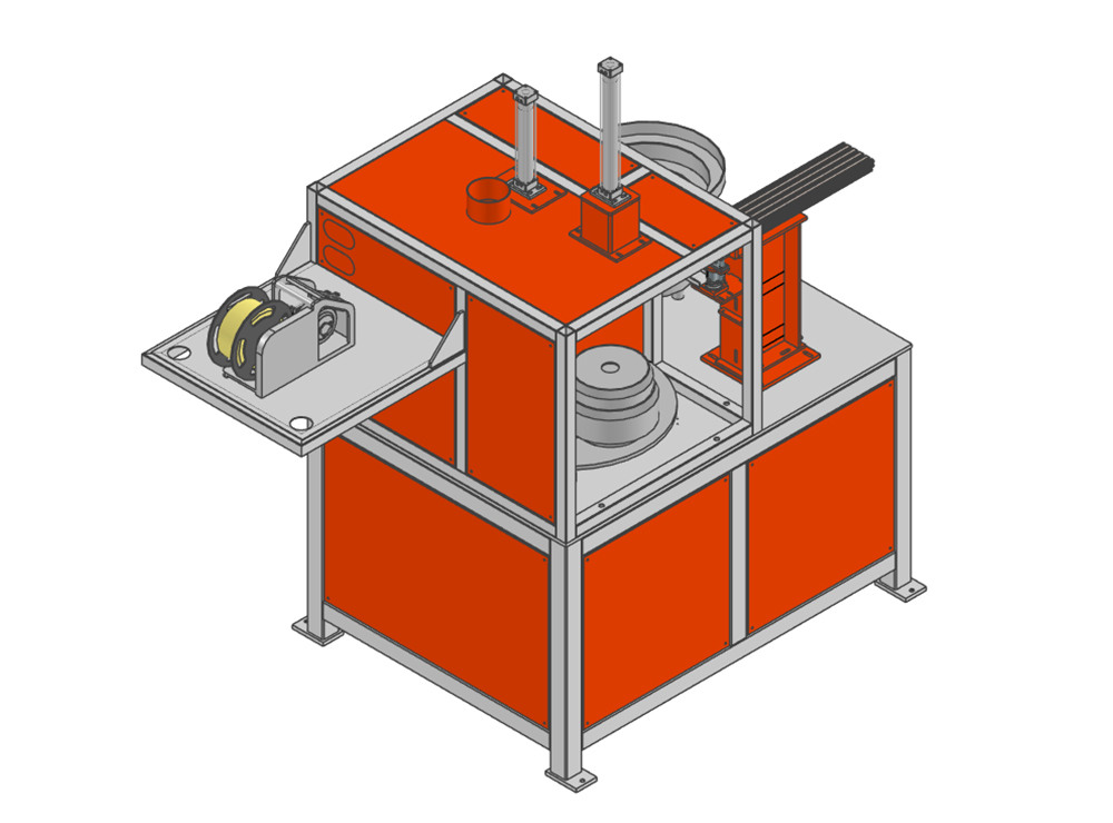
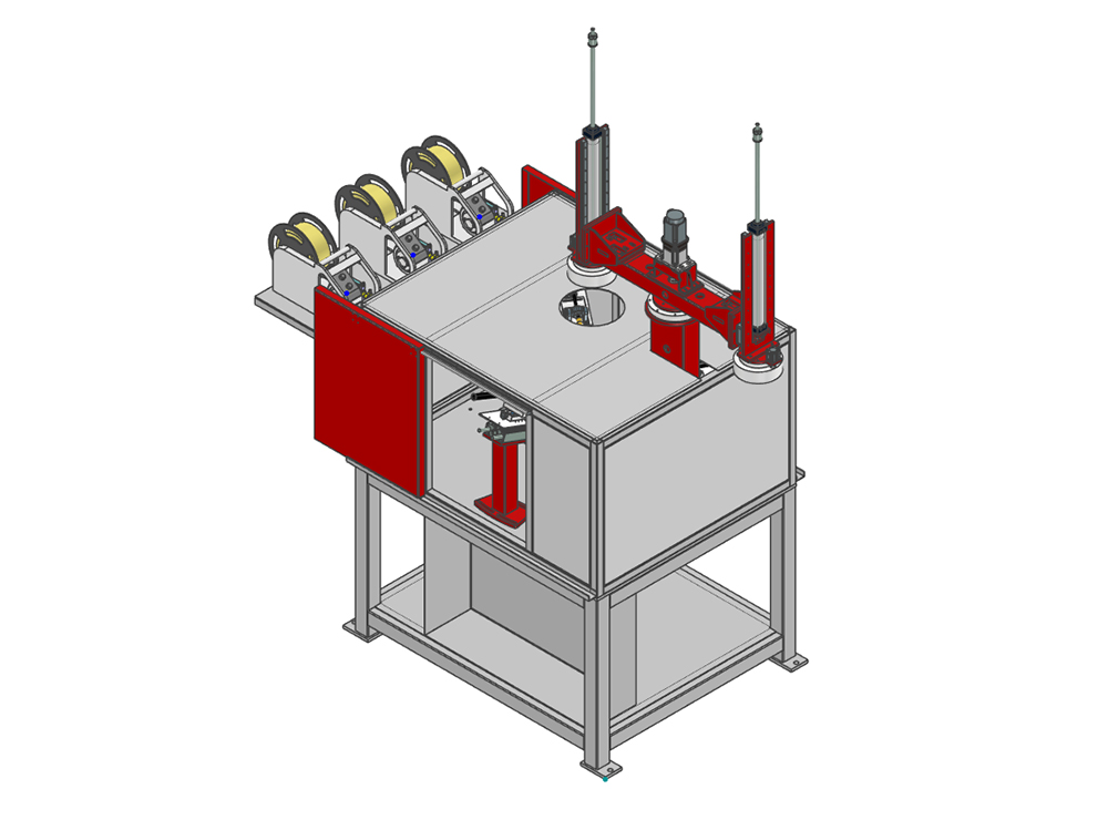
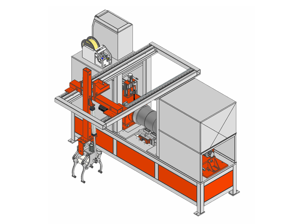
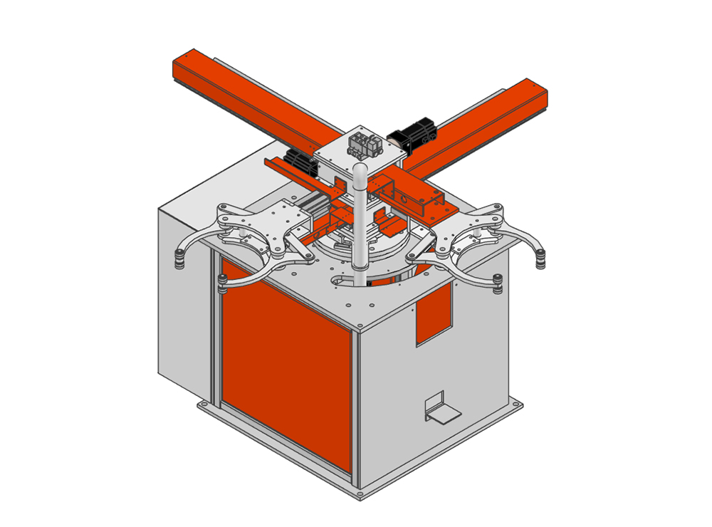
How Beading and Joggling Improve LPG Cylinder Assembly Accuracy depends on controlling the shell profile before welding. Beading shapes and stabilizes the cylinder shell edge or profile, while joggling creates a controlled offset or overlap that improves concentric fit-up, supports the joint during circumferential welding, and reduces shell mismatch. I use both operations as dimensional-control steps rather than treating them as cosmetic forming processes.
!
Key Takeaways
- Beading controls shell geometry, while joggling establishes repeatable overlap and circumferential joint fit-up.
- Accurate forming reduces eccentric seams, uneven overlap, weld distortion, and repeated manual adjustment.
- Trimming must precede joggling because inconsistent shell edges create unstable offsets and poor welding preparation.
- Dimensional inspection verifies alignment, while weld inspection verifies penetration, continuity, porosity, and leakage resistance.
- Equipment selection should match cylinder diameter, material thickness, production volume, automation level, and inspection requirements.
- Shuofang provides LPG cylinder machinery, production-line integration, installation support, training, and one-year equipment warranty coverage.
What Are Beading and Joggling in LPG Cylinder Manufacturing?
Beading is a controlled forming operation that creates a circular reinforcement, transition, or profile around the LPG cylinder shell. Depending on the cylinder design, it can improve shell rigidity, stabilize the body during handling, and maintain a consistent geometric reference for later assembly. Beading is normally performed after shell forming and before final welding or downstream finishing operations.
Joggling is an edge-forming operation that produces a controlled step, offset, or overlap between two shell sections. The offset allows one shell edge to locate consistently against another, reducing abrupt mismatch at the circumferential joint. Unlike beading, which primarily changes the shell profile or adds a circular formed feature, joggling primarily controls the relationship between mating edges.
The two processes usually fit into a broader LPG cylinder manufacturing sequence:
- Sheet preparation: Steel sheets are cut, inspected, and prepared for deep drawing or shell forming.
- Shell forming: Presses or deep-drawing equipment produce the upper and lower shell sections.
- Trimming: Excess material is removed to establish a defined shell edge.
- Beading or profile forming: The shell receives its required circular geometry or reinforcement.
- Joggling: A controlled offset or overlap is formed at the joining edge.
- Fixturing and assembly: Shell halves are positioned concentrically using a dedicated fixture.
- Circumferential welding: The joint is rotated through a controlled welding path.
- Inspection and finishing: Welds, dimensions, leakage resistance, surface condition, and pressure performance are checked.
The exact sequence depends on cylinder design, material thickness, applicable standards, and the production line configuration. However, trimming must provide a stable reference before joggling, because an uneven or angled shell edge transfers directly into the overlap condition. If the edge is not consistent, the machine may produce a nominally correct joggle while the assembled cylinder remains eccentric.
How Beading and Joggling Improve LPG Cylinder Assembly Accuracy
How Beading Controls Shell Shape and Alignment
Beading improves LPG cylinder assembly accuracy by creating a repeatable shell profile that operators and fixtures can reference. A consistent bead reduces local waviness and helps the shell maintain its intended circular form during handling. This matters because a shell that is round at one measurement position but distorted at another can produce variable welding gaps during rotation.
I recommend checking the bead at several angular positions rather than measuring only once. For example, a manufacturer may inspect at 0°, 90°, 180°, and 270° around the circumference, then record bead height, radial position, and local deformation. An internal production limit might specify that bead-height variation remains within 0.5 mm, but the correct value must be confirmed against the cylinder drawing, material grade, wall thickness, and governing standard.
Beading also affects the stiffness of the shell during assembly. If the shell wall deflects when clamped, the joint location can shift as the welding torch or electrode moves around the cylinder. A stable bead profile reduces this movement and gives the fixture a more predictable surface to support.
How Joggling Improves Joint Fit-Up
Joggling improves LPG cylinder accuracy by creating a controlled overlap or offset between mating shell edges. The joggle depth should be measured from a defined datum, not estimated visually by the operator. A practical inspection record can include joggle depth, overlap width, axial offset, circumferential continuity, and the maximum local mismatch.
For example, if a design specifies a 2.0 mm joggle depth, production control should define an acceptable range such as 1.8–2.2 mm only after engineering validation. This example is not a universal requirement; the allowable range must account for sheet thickness, joint design, welding process, and applicable pressure-vessel rules. The important principle is that the joggle must be controlled as a measured dimension rather than treated as an approximate formed feature.
Joggling also limits sudden changes in shell position at the joint. When the overlap is consistent, the fixture can hold the shell sections with less manual correction, and the welding system can maintain a more stable torch-to-joint relationship. This reduces the risk of incomplete fusion, excessive reinforcement, undercut, and inconsistent penetration caused by changing joint geometry.
How the Two Processes Work Together
Beading and joggling solve different dimensional problems, so one cannot automatically replace the other. Beading controls the shell profile and stiffness, while joggling controls the mating relationship between the shell edges. Used together, they create a more stable foundation for fixturing and circumferential welding.
I evaluate their combined effect through three measurements: shell concentricity, overlap consistency, and weld-track stability. Concentricity can be checked with a dial indicator or coordinate measurement method, overlap can be checked with depth gauges or calibrated fixtures, and weld-track stability can be evaluated through seam-tracking records and visual or nondestructive inspection. These measurements separate dimensional accuracy from weld-quality accuracy.
| Control area | Main process influence | Recommended verification |
|---|---|---|
| Shell circularity | Shell forming and beading | Diameter measurement at multiple angular positions |
| Edge height | Trimming | Height gauge or calibrated inspection fixture |
| Joggle depth | Joggling | Depth gauge, profile gauge, or fixture sensor |
| Overlap width | Joggling and fixturing | Cross-section check or dimensional gauge |
| Concentricity | Shell assembly | Dial indicator, laser measurement, or coordinate check |
| Weld tracking | Rotation and seam control | Tracking record and visual inspection |
| Weld integrity | Welding process | Nondestructive testing, leakage testing, and pressure testing |
A Measurement-Based Workflow for Accurate Assembly
Form and Trim the Shell Consistently
The first control point is sheet and shell preparation. Material thickness, blank diameter, forming direction, and lubrication conditions can influence springback and shell dimensions. I would establish incoming material checks and record shell height, diameter, edge condition, and visible deformation before the shell enters the trimming operation.
Trimming should create a clean and repeatable edge around the entire circumference. Burrs, sharp local steps, or variations in edge height can prevent the joggling tool from applying uniform pressure. If the trimmed edge varies by more than the internal drawing limit, the shell should be corrected or rejected before joggling rather than adjusted later at the welding station.
Set the Joggle Using a Defined Datum
A joggle machine should be set from a fixed mechanical or digital datum that corresponds to the cylinder drawing. The operator should verify the first component of every batch and repeat the measurement after tool changes, material changes, or extended production runs. Recording only machine settings is insufficient because tool wear, springback, and sheet variation can change the actual formed result.
A useful setup record includes nominal joggle depth, measured joggle depth, overlap width, shell identification, tool number, operator, and inspection time. For higher-volume lines, a statistical process chart can show whether the dimension is drifting toward its upper or lower limit. This allows maintenance or adjustment before the joint becomes visibly misaligned.
Fixture the Shell Before Welding
Fixturing controls the relationship between the upper and lower shell sections. The fixture should support the shell close to the joint, center the components on a common axis, and prevent rotation-induced movement during welding. Clamping pressure must be sufficient to hold the parts without creating local dents or permanently distorting the shell.
I recommend checking runout before welding by rotating the assembled cylinder through at least one complete revolution. If a dial indicator shows excessive radial movement, the operator should identify whether the cause is shell ovality, uneven joggle depth, fixture wear, or incorrect seating. Welding should not begin until the source of the runout is understood.
Select the Welding and Tracking Method
The welding process must match the material, thickness, joint design, and required production rate. Circumferential welding may use automatic or semi-automatic equipment with controlled rotation, programmed travel speed, monitored current, voltage, shielding gas, and torch position. The selected process should maintain the required heat input while limiting distortion around the cylinder circumference.
Seam tracking is particularly important when the joint position changes slightly during rotation. Laser or mechanical tracking can help the torch follow the actual joint rather than relying only on a fixed position. Shuofang identifies laser tracking as part of its circumferential welding equipment and provides automated, semi-automated, and segmented LPG cylinder production-line configurations.
A welding setup sheet should include joint type, wire or electrode specification, current range, voltage range, travel speed, shielding-gas flow, rotation speed, and preheating requirements where applicable. These values should come from qualified welding procedures rather than being copied from an unrelated cylinder model. Operators should also record any arc interruption, tracking alarm, rotation stop, or visible weld defect.
Choosing Beading and Joggling Machines for LPG Cylinder Production
When selecting LPG cylinder beading and joggling machines, I begin with the cylinder drawing rather than the machine catalog. The critical inputs include cylinder diameter, shell height, sheet thickness, steel grade, joggle geometry, bead profile, required cycle time, and the number of cylinder models. A machine designed for one diameter may not provide sufficient tooling range or adjustment accuracy for a multi-model production line.
| Selection factor | Why it affects accuracy | Evidence to request |
|---|---|---|
| Diameter range | Determines tooling and fixture compatibility | Approved model range and sample trials |
| Sheet thickness | Affects forming force and springback | Rated thickness range and test records |
| Joggle depth | Controls overlap and joint fit-up | Measured sample dimensions |
| Automation level | Affects repeatability and labor dependence | Cycle sequence and operator tasks |
| Tool adjustment | Determines changeover consistency | Adjustment method and calibration procedure |
| Inspection integration | Supports process verification | Gauges, sensors, and data records |
| Maintenance access | Influences dimensional drift | Tool-life guidance and spare-parts list |
For a small manufacturer, a semi-automatic line may be appropriate when product variation is high and production volume is moderate. A larger factory may require automated transfer, integrated fixturing, automatic welding, and in-line inspection to reduce manual handling. The correct choice depends on measured capacity, staffing, changeover frequency, and the cost of rejected cylinders.
The Beading Joggling Cleaning Machine should also be considered as part of the process chain rather than as an isolated unit. Cleaning or surface preparation after forming can remove oil, scale, burrs, and forming residue that would otherwise affect welding stability or inspection results. The cleaning method must be compatible with the cylinder material, coating plan, worker-safety requirements, and wastewater or waste-handling controls.
Shuofang, formally Henan Shuofang Intelligent Equipment Co., Ltd., presents LPG cylinder production equipment covering deep drawing, trimming, joggling, polishing, welding, heat treatment, coating, testing, and related operations. Its published company information states that it has more than 10 years of experience, a production base exceeding 20,000 square meters, annual output value above 70 million yuan, and production-line case work involving annual capacity of 1.68 million cylinders. These figures describe the supplier’s stated operating scale, but a buyer should still request model-specific acceptance data before placing an order.
LPG Cylinder Assembly Quality Control After Beading and Joggling
Quality control should distinguish between dimensional accuracy and weld-quality accuracy. Dimensional checks verify shell diameter, circularity, edge height, joggle depth, overlap, concentricity, and bead geometry. Weld checks verify bead continuity, penetration, surface condition, defect presence, leakage resistance, and pressure performance.
A practical control plan may include the following inspections:
- Incoming sheet thickness, width, surface condition, and material identification.
- Shell height, diameter, ovality, and edge condition after forming.
- Trim height and burr condition before joggling.
- Joggle depth, overlap width, and circumferential continuity.
- Assembly concentricity and radial runout before welding.
- Welding parameters, rotation speed, seam tracking, and alarm records.
- Visual inspection and applicable nondestructive testing of the circumferential seam.
- Air-leakage testing, hydrostatic testing, and final dimensional inspection.
Inspection frequency should be based on risk and process stability. First-piece approval is necessary after setup, while periodic checks should be increased after tool maintenance, material changes, unexplained weld defects, or repeated fixture adjustments. Measuring only the finished cylinder can hide the operation that created the error, so I prefer recording data at forming, trimming, joggling, fixturing, welding, and final inspection stages.
Troubleshooting Common Alignment Failures
| Observed failure | Likely cause | Corrective action |
|---|---|---|
| Uneven overlap | Variable joggle depth or trimmed edge | Check trim height, tool pressure, and joggle datum |
| Shell mismatch | Oval shell or incorrect fixture seating | Measure shell circularity and inspect fixture supports |
| Eccentric circumferential seam | Off-center assembly or fixture runout | Check axis alignment and rotate before welding |
| Distorted weld area | Excessive heat input or weak clamping | Review welding parameters and support placement |
| Inconsistent bead geometry | Tool wear, springback, or material variation | Inspect tooling and verify sheet thickness |
| Weld tracking deviation | Joint position changes during rotation | Calibrate tracker and correct shell runout |
| Local leakage | Porosity, incomplete fusion, or joint gap | Review surface cleaning, parameters, and fit-up |
| Repeated manual correction | Unstable upstream dimensions | Add process measurements before assembly |
Operator safety must be included in each correction. Forming tools, rotating fixtures, welding arcs, hot shells, sharp trimmed edges, and cleaning equipment create separate hazards that require guarding, lockout procedures, personal protective equipment, ventilation, and documented training. A production line that improves dimensional accuracy but increases exposure to pinch points or welding fumes is not an acceptable process improvement.
Best Practices for Accurate LPG Cylinder Assembly
I recommend beginning with a controlled drawing review that identifies all functional dimensions: shell diameter, wall thickness, trim height, bead location, joggle depth, overlap, weld size, and inspection points. Each dimension should have a measurement method and an accountable process owner. If a dimension cannot be measured reliably on the factory floor, it should not be left as an informal operator judgment.
The second practice is to qualify the complete chain rather than approving beading or joggling separately. A shell can pass a bead-height check and still produce poor weld fit-up if trimming or fixture alignment is incorrect. Trial production should therefore evaluate formed geometry, assembly runout, weld tracking, weld inspection, leakage testing, and pressure testing as connected results.
The third practice is to maintain traceable production records. Each cylinder batch should be linked to material information, machine settings, tool identification, inspection results, welding data, and nonconformance actions. This allows the manufacturer to determine whether a defect originated in shell forming, trimming, joggling, fixturing, welding, or post-weld handling.
Conclusion
How Beading and Joggling Improve LPG Cylinder Assembly Accuracy can be answered through their separate but connected functions. Beading stabilizes the shell profile and provides consistent geometry, while joggling controls edge offset, overlap, and joint fit-up before circumferential welding. When trimming, fixturing, rotation, seam tracking, and inspection are controlled at the same time, manufacturers can reduce shell mismatch, eccentric seams, weld distortion, and repeated manual adjustment.
My recommended next step is to define the cylinder drawing requirements first, then test the complete sequence from shell forming through final inspection. Measure joggle depth, overlap, concentricity, bead geometry, weld-track stability, leakage resistance, and pressure-test results using documented acceptance limits. For equipment evaluation, compare machine capability, tooling range, automation level, inspection integration, safety provisions, service support, and model-specific sample data rather than relying only on stated production capacity.