Common Welding Defects in LPG Cylinder Production and Their Solutions
Oct.28, 2026
In my experience, Common Welding Defects in LPG Cylinder Production and Their Solutions must be treated as a pressure-containment and process-control issue, not only as a cosmetic welding topic. Porosity, cracks, undercut, slag inclusion, lack of fusion, and incomplete penetration can create leakage paths or reduce fatigue resistance in the cylinder shell. I therefore connect defect prevention with material preparation, fit-up, welding parameters, inspection records, and final pressure testing.
!
Why Welding Quality Affects LPG Cylinder Safety
An LPG cylinder is exposed to internal pressure, filling cycles, transport vibration, temperature changes, and repeated handling. A weld that appears acceptable during a visual inspection may still contain internal discontinuities capable of developing into leakage or fatigue damage. For that reason, I evaluate weld integrity at several levels: surface appearance, dimensional accuracy, pressure containment, leak tightness, and internal soundness.
The production stage also matters. Defects can originate during shell forming, longitudinal or circumferential seam welding, valve-neck welding, handle welding, or foot-ring attachment. The risk is different at each location: a defect in a pressure boundary requires stricter disposition than a small surface imperfection on a non-pressure accessory.
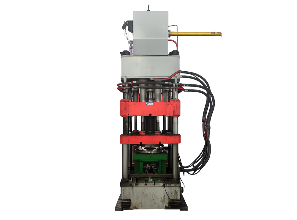
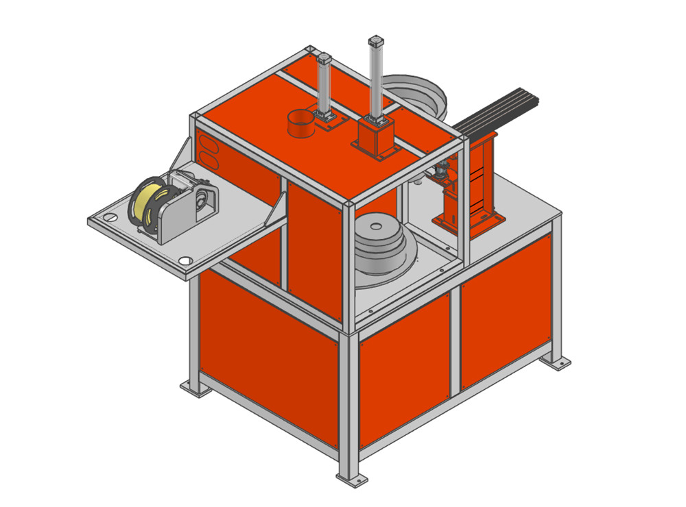
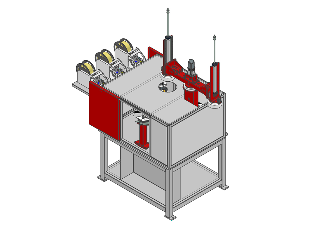
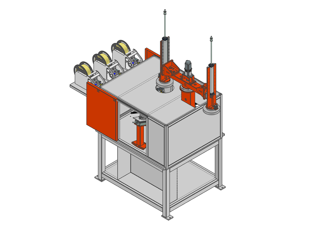
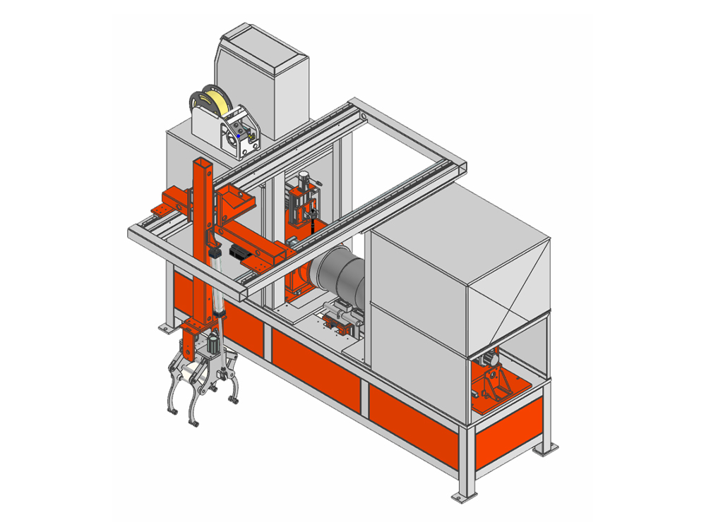
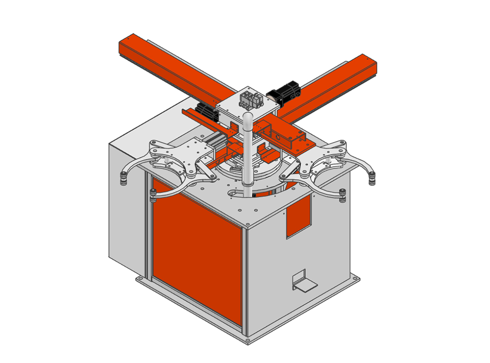
Shuofang’s LPG Cylinder Welding Line approach illustrates why equipment selection and inspection should be considered together. Its automatic circular seam welding equipment is designed for steel cylinders with diameters of 280–320 mm and heights of 260–300 mm. The listed HH-15-320 system has a total power of 23 kW and a welding rate of 0.5–0.7 cylinders per minute, making consistent fixture alignment and parameter control important for repeated production.
Common Welding Defects in LPG Cylinder Production
The most common defects are porosity, cracks, undercut, overlap, slag inclusion, lack of fusion, incomplete penetration, burn-through, excessive spatter, and dimensional distortion. Their consequences differ according to location, depth, length, and whether the weld forms part of the pressure boundary.
- Porosity creates gas pockets inside or on the surface of the weld.
- Cracks can propagate under pressure cycling and normally require rejection or qualified repair.
- Undercut reduces wall thickness beside the weld toe.
- Slag inclusion leaves nonmetallic material trapped in the weld.
- Lack of fusion means the weld metal has not bonded correctly with the base metal.
- Incomplete penetration leaves an unfused region through part of the joint thickness.
- Burn-through produces excessive penetration, a hole, or severe local thinning.
- Overlap and excessive spatter indicate poor bead control and can conceal more serious discontinuities.
| Defect | Common location | Main causes | Prevention | Inspection and disposition |
|---|---|---|---|---|
| Porosity | Circumferential or neck welds | Oil, moisture, rust, unstable shielding gas | Clean surfaces, control gas flow, dry consumables | Visual, radiographic or ultrasonic examination; remove and re-weld if unacceptable |
| Crack | Pressure boundary or heat-affected zone | Excessive restraint, hydrogen, rapid cooling, high stress | Qualified procedure, controlled heat input, correct consumables | Visual and NDT; usually reject unless repair is formally qualified |
| Undercut | Weld toe | Excessive current, high travel speed, incorrect angle | Adjust current, voltage, travel speed, torch position | Visual and dimensional check; grind and repair when permitted |
| Slag inclusion | Multi-pass welds | Inadequate cleaning or poor bead overlap | Remove slag between passes and maintain angle | Radiography or ultrasonic testing; excavate and re-weld |
| Lack of fusion | Sidewall, root, or inter-pass region | Low heat input, contamination, poor torch angle | Correct fit-up, current, speed, and joint preparation | Ultrasonic or radiographic examination; remove defective area |
| Incomplete penetration | Root of seam weld | Small root gap, poor alignment, insufficient energy | Control gap, centering, current, and travel speed | NDT and leak testing; repair only under approved procedure |
| Burn-through | Thin shell or root area | Excessive current, slow travel, excessive gap | Reduce heat input and improve support | Visual and dimensional inspection; reject or qualified repair |
| Overlap | Weld toe | Excessive deposition or low travel speed | Adjust wire feed and torch movement | Visual inspection; remove if it affects profile or fusion |
LPG Cylinder Weld Porosity and Prevention
Porosity occurs when gas becomes trapped as molten weld metal solidifies. In LPG cylinder production, the most frequent sources are oil, moisture, mill scale, paint residue, rust, contaminated wire, damp electrodes, and insufficient shielding-gas coverage. Air movement around the welding station can also disturb shielding and introduce nitrogen or oxygen into the molten pool.
I prevent porosity by treating cleaning as a measurable production operation rather than an informal preparation step. The shell edge should be free from visible oil, loose scale, moisture, and coating residue, while the filler wire and contact tip should be checked at defined intervals. Shielding-gas flow, hose condition, regulator stability, and nozzle distance should be recorded because a small gas-flow change can affect an entire production batch.
When porosity is found, I first isolate the cylinder lot and compare the defect location with the welding station, gas supply, material batch, and operator record. A shallow isolated pore may be removed if the applicable cylinder code permits repair, but clustered porosity or porosity crossing a pressure seam requires a formal engineering decision. The repaired area must be re-inspected using the same or a more sensitive method used for the original weld.
Cracks, Undercut, Slag Inclusion, and Burn-Through
Cracks are among the most serious welding defects in LPG cylinders because they provide a sharp discontinuity where stress can concentrate. They may occur in the weld metal, fusion boundary, or heat-affected zone. Causes include excessive restraint, unsuitable consumables, hydrogen contamination, rapid cooling, excessive heat input, or residual stress from poor fit-up.
I do not treat a crack as a cosmetic repair. The affected area must be identified, excavated to sound metal, examined to confirm complete removal, and repaired using a qualified procedure if the governing standard allows repair. If the crack extends into the parent metal, appears repeatedly, or cannot be removed without reducing the required wall thickness, rejection is the safer disposition.
Undercut reduces the effective section beside the weld toe and may become a fatigue initiation point. It is commonly associated with excessive current, high travel speed, a long arc, or an incorrect electrode or torch angle. Corrective actions include adjusting current and travel speed, improving torch manipulation, and checking whether the welding position or fixture is forcing the operator into an unstable angle.
Slag inclusion usually results from inadequate cleaning between passes, poor bead placement, or incorrect electrode manipulation. The remedy is not simply to add another cover pass. I remove the affected material, clean the excavation, verify the geometry, and then re-weld under the approved procedure. Burn-through requires particular attention because it can produce a hole, excessive root penetration, or localized thinning that is difficult to assess from the outside.
Lack of Fusion vs Incomplete Penetration
Lack of fusion and incomplete penetration are different defects, although both can reduce pressure-boundary integrity. Lack of fusion occurs when weld metal does not bond with the sidewall, previous pass, or root surface. Incomplete penetration occurs when the weld does not extend through the intended joint thickness at the root.
Lack of fusion is often caused by low heat input, excessive travel speed, surface contamination, incorrect torch angle, or poor access to the joint. Incomplete penetration is more closely connected with root gap, edge preparation, alignment, electrode position, and the energy delivered to the root. Both defects may be hidden beneath an apparently acceptable bead profile.
I control these defects through fit-up gauges, fixture maintenance, sample cross-sections during procedure qualification, and process monitoring during production. Where the joint design and cylinder standard require internal examination, radiography or ultrasonic testing should be selected according to material thickness, geometry, defect orientation, and qualified inspection capability.
Why Welding Defects Occur in LPG Cylinder Manufacturing
The root causes usually come from six interacting areas: materials, fit-up, welding parameters, shielding gas, consumables, and operator technique. A clean material can still produce defects if the shell halves are misaligned or the root gap varies around the circumference. Similarly, a correctly aligned joint can fail when current, voltage, travel speed, or wire feed changes beyond the qualified range.
For welding quality control for pressure vessels, I recommend linking every cylinder or production batch to material heat information, forming records, welding procedure identification, operator identity, machine settings, inspection results, and repair history. This traceability allows the manufacturer to determine whether a defect is isolated or connected to a broader process shift.
Statistical monitoring is useful for automated lines. I would track defect frequency by welding station, shift, material batch, cylinder model, and defect category. A rising rate of porosity may indicate gas-system deterioration, while increasing lack of fusion may indicate contact-tip wear, fixture movement, or a drift in heat input. The objective is to identify the process change before defective cylinders accumulate.
LPG Cylinder Seam Weld Inspection Methods
No single inspection method detects every defect. I use a layered inspection workflow so that surface, dimensional, pressure, leakage, and internal conditions are assessed separately.
Visual and Dimensional Inspection
Visual inspection should begin after welding and again after cleaning, grinding, and surface treatment. The checklist should cover bead continuity, weld profile, undercut, overlap, visible cracks, spatter, arc strikes, burn-through, distortion, and incomplete areas. Dimensional checks should confirm shell alignment, circularity, weld position, neck location, foot-ring alignment, and any dimensions specified by the cylinder design.
Air Leakage and Pressure Testing
Air leakage testing checks whether the finished cylinder has a leak path that could allow LPG to escape. Hydrostatic testing evaluates pressure containment and deformation behavior under the specified test procedure. These tests are not substitutes for weld inspection because a small defect may not leak during one test condition but may still reduce fatigue resistance or violate the applicable acceptance criteria.
Radiographic and Ultrasonic Testing
Radiographic testing can reveal volumetric discontinuities such as porosity, slag inclusion, and incomplete penetration, depending on geometry and technique. Ultrasonic testing can detect planar defects such as lack of fusion and cracks, but sensitivity depends on calibration, probe selection, surface condition, and operator qualification.
The inspection plan should define test coverage, calibration frequency, acceptance criteria, inspector qualification, equipment identification, and record retention. Acceptance limits must come from the applicable cylinder standard, design approval, and regulatory authority rather than from a generic fabrication table.
Production-Stage Defect Matrix and Corrective Actions
I use the following matrix during production meetings because it connects the defect with its likely stage and response.
| Production stage | Typical defect | Immediate control | Follow-up action |
|---|---|---|---|
| Material preparation | Porosity, lack of fusion | Stop affected material and clean surfaces | Verify supplier batch, storage, and surface condition |
| Shell forming | Misalignment, incomplete penetration | Check tooling and shell geometry | Repair or replace distorted components |
| Joint fit-up | Lack of fusion, burn-through | Measure gap and offset around the joint | Reset fixture, replace worn clamps, re-qualify setup if needed |
| Welding | Undercut, cracks, slag inclusion | Hold the lot and inspect machine settings | Correct parameters, consumables, gas supply, and technique |
| Post-weld cleaning | Hidden slag or grinding damage | Inspect before coating or heat treatment | Rework under documented repair procedure |
| Final inspection | Leakage or pressure failure | Quarantine cylinder and associated lot | Root-cause investigation and expanded inspection |
Repair or Reject: How I Make the Decision
A defective weld is not automatically repairable. I first determine whether the defect affects a pressure boundary, whether the full defect can be removed, whether the remaining wall thickness will stay within design requirements, and whether the repair method has been qualified.
Repair normally requires defect removal, confirmation that sound metal has been reached, controlled re-welding, post-repair visual inspection, and repeat NDT or pressure testing as required. The repair record should include cylinder identification, defect type, location, removal method, welding procedure, operator, inspection results, and final disposition.
I recommend rejection or scrapping when a crack extends into the parent metal, repeated repairs reduce the required wall thickness, distortion prevents dimensional compliance, leakage remains after qualified repair, or the defect cannot be fully characterized. For pressure vessels, undocumented repair is not an acceptable substitute for a controlled repair procedure.
Equipment and Process Control for an LPG Cylinder Welding Line
Automation reduces variation only when the machine, fixture, sensor, and welding procedure are maintained as one system. Shuofang describes automatic and semi-automatic LPG cylinder production solutions that include circumferential welding, valve-neck welding, handle and base welding, hydrostatic testing, and airtightness testing. Its listed circular seam system uses laser tracking and is specified for cylinder dimensions of 280–320 mm in diameter and 260–300 mm in height.
For a production line, I would verify the following before approving equipment:
- Weld current, voltage, wire feed, travel speed, and heat input ranges
- Fixture repeatability and shell alignment control
- Shielding-gas monitoring and alarm functions
- Torch position, nozzle condition, and contact-tip wear limits
- Automatic seam tracking and end-of-weld control
- Inspection data storage by cylinder or production batch
- Access for visual, dimensional, leak, hydrostatic, radiographic, or ultrasonic testing
- Repair and maintenance records linked to defect trends
The equipment supplier’s operating data should also be compared with the factory’s capacity target. A listed welding rate of 0.5–0.7 pieces per minute corresponds to approximately 30–42 pieces per hour before allowance for loading, unloading, inspection, stoppage, and maintenance. That distinction matters when calculating actual output and estimating the effect of reduced manual handling.
How to Prevent Welding Defects in LPG Cylinder Production
I recommend a controlled prevention program built around five actions:
- Qualify the welding procedure for each joint type, material range, thickness range, position, and applicable cylinder standard.
- Qualify welders and machine operators so that manual and automated operations are performed within documented limits.
- Control material and fit-up through cleaning requirements, storage conditions, gap measurements, alignment checks, and fixture maintenance.
- Monitor welding variables including current, voltage, travel speed, gas flow, wire feed, and heat input.
- Verify the finished cylinder using visual, dimensional, leak, hydrostatic, and appropriate NDT methods.
I would also establish a first-piece approval process after setup, tooling replacement, consumable change, maintenance intervention, or model change. Production should not continue solely because the machine is running; the first cylinder must demonstrate that the complete process remains within the qualified range.
Conclusion
Common Welding Defects in LPG Cylinder Production and Their Solutions center on controlling porosity, cracks, undercut, slag inclusion, lack of fusion, incomplete penetration, burn-through, and distortion before they become pressure-containment failures. I prevent these defects by controlling material cleanliness, fit-up, shielding gas, consumables, heat input, operator technique, and equipment condition.
The inspection workflow should combine visual and dimensional checks with air leakage testing, hydrostatic testing, radiography, or ultrasonic testing according to the cylinder design and governing requirements. Defect records should be connected to material batches, welding parameters, operators, machines, repairs, and final test results.
For manufacturers evaluating an LPG Cylinder Welding Line, I recommend comparing not only rated production speed but also fixture accuracy, seam tracking, parameter recording, inspection integration, repair control, and after-sales technical support. Shuofang’s production-line offering includes automatic and semi-automatic equipment, circumferential welding systems, and pressure and airtightness testing equipment, providing a practical reference for building a traceable welding and inspection process.